One continuous belt across the working width
In a conventional arrangement, transverse spiked lags are carried on several narrow straps. Separate fabric backing closes the gaps between the lags. This creates spaces between the wood and backing where fibres can become packed.
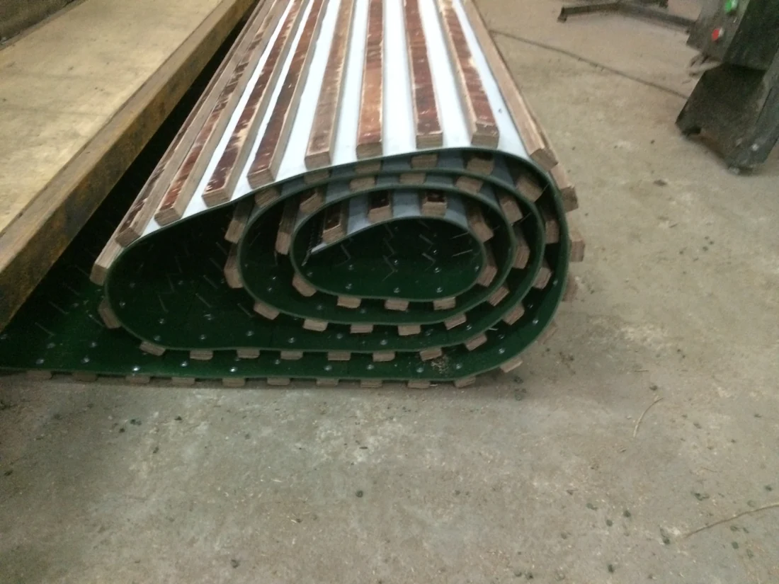
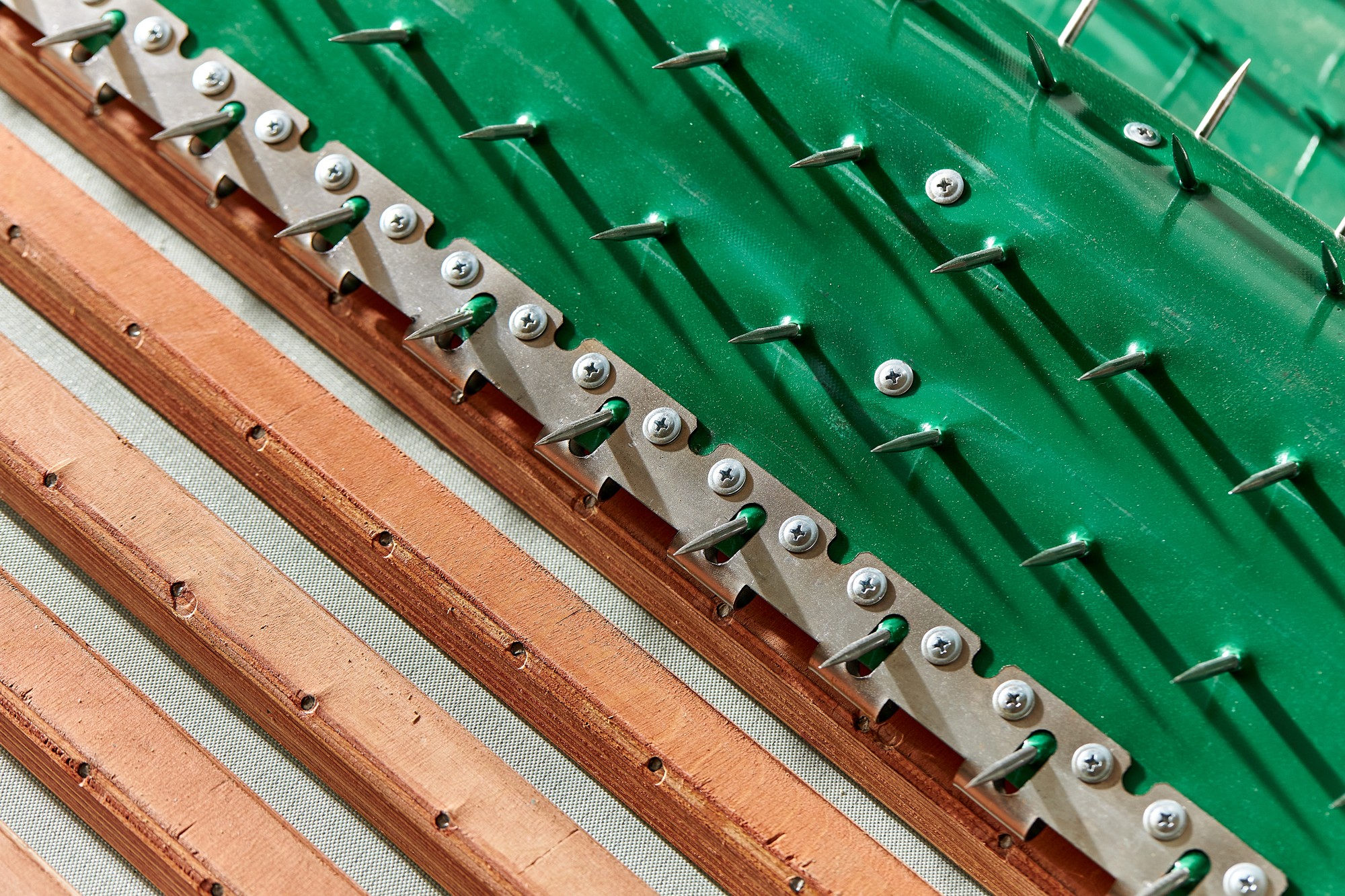
Our selected construction uses a continuous PVC belt for both the load-carrying base and the surface retaining the fibres. Plywood lags are mounted inside the loop; steel pins pass through the belt and project outwards. The surface between the pins remains continuous, without a separate fabric backing under the lags.
A working surface that is easier to clean
Removing the former spaces between the lags and fabric backing reduces the places where old material remains trapped. This is useful when changing fibre type, colour or blend composition.
The smooth outer surface also helps the machine’s stripper roller, comb or other discharge device release the material. After installation, accumulation and ease of cleaning are checked with the production material and the existing feeder settings.
Pins selected for the fibre and feeder
Pin length, diameter, inclination, spacing and number of rows are selected for fibre length and fineness, bulk density, tuft size and required throughput. With suitable pins and settings, the conveyor can handle wool, cotton, man-made fibres and prepared recycled material.
Applications include card hopper feeders, bale openers, blending and dosing units, and the feed hoppers of textile waste tearing lines. In nonwoven production, the conveyor operates upstream of web formation, at the fibre preparation and feeding stages.
Feed uniformity depends on the complete feeder: hopper filling, pin geometry, belt speed and the levelling and stripping devices. Accurate weight dosing requires weighing equipment, sensors and controls. The full-width belt improves construction and maintenance; it does not itself stabilise the feed.
A common carrier for the lags and joint
The reinforced PVC belt carries tensile loads across its width and supports the connecting joint on the same continuous base. The belt grade is chosen for the operating temperature, speed, wear, roller diameters and required flexibility. Antistatic properties are specified according to the material and equipment requirements.
With the lags mounted inside, operating forces tend to press them against the belt, with loads transferred through the fasteners and pins. The lags also form the contact surface with the drive roller. Reliable friction drive depends on belt tension, surface condition and actual load.
Plywood lags and pin retention
Cross-oriented veneers help moisture-resistant plywood retain its shape and reduce splitting along the grain. The plywood grade, thickness, quality and edge treatment are selected for the working conditions. Stable lag geometry helps maintain the specified pin positions.
The pins are held in the lag and pass through the resilient PVC belt. The relatively low mass of plywood limits the weight of the moving assembly, while replaceable lags allow local repairs.
Keeping the wooden lag bodies inside the loop separates them from the material flow and can reduce the transfer of fragments if a lag is damaged. The exposed pins still require routine inspection.
A sectional hinge joint for mounting and repair
The joint is attached through the PVC belt to a supporting lag. This provides a wider attachment zone and transfers load into the lag, instead of relying on the belt edge alone.
The removable connection allows the loop to be opened for installation, a damaged lag or joint section to be replaced, and sound components to be reused. This version can be installed and replaced with standard workshop tools, without a specialised staple installation tool. Joint dimensions and fasteners are matched to the width, rollers, working tension and available space.
Manufacture and retrofit for an existing machine
We specify working width, endless belt length, tensioning range, roller diameters and internal feeder clearances, together with lag dimensions and spacing, pin geometry and the connecting joint. A replacement can be prepared for the existing assembly without replacing the complete feeder.
Moisture-resistant plywood is selected for standard dry feeding. Resin-impregnated plywood may be considered for higher humidity or abrasion, taking its mass and cost into account. The complete assembly is evaluated for material accumulation, cleaning, joint performance, running stability and interaction with the levelling and stripping devices.
An example configuration
The described version uses the dimensions below. These are parameters of one construction, rather than fixed dimensions for every order. The joint, pins and belt are specified for the customer’s machine.
- Conveyor working width
- Up to 4 m
- Joint section length
- 1150 mm
- Steel connecting rod diameter
- 6 mm
- Joint fasteners
- 25 mm spacing; fastening line at least 25 mm from the belt edge